With the popularization of computer technology, cement trailer computer finite element analysis has been more and more widely used in engineering analysis and product development and design, and computer finite element analysis has become an efficient and convenient way to solve the problem of calculating and analyzing large and complex engineering data. Currently, computer finite element analysis is widely used in many fields such as machinery manufacturing, material forming and processing, electronic and electrical appliance development, automobile structure, aerospace materials, national defense and military design, civil engineering and construction, shipbuilding, petrochemical industry, energy extraction, railway transportation, and theoretical scientific research.
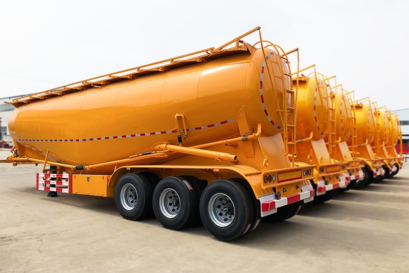
In this section, we simulate and analyze the 30m3 cement trailer (hereinafter referred to as “cement trailer”) under different driving conditions through computer finite element analysis technology to verify its strength.
1. Establishment of cement trailer geometry model and finite element meshing
In practice, the structure of the object is often complex, and if the modeling is done completely according to the solid structure, it will make the model more complicated and greatly increase the computational analysis.
In practice, the structure of the object is often complex, and if the modeling is done completely according to the solid structure, it will make the model more complicated and greatly increase the time of calculation and analysis, or even impossible. For this reason, when building the geometric model of a component, the difficulty and workload of the analysis can be reduced by simplifying the model under certain conditions.
The workload can be reduced by simplifying the model under certain conditions. In this paper, in order to facilitate the modeling of a 30m3 cement trailer, the following treatments were made.
(1) The influence of the weld on the structure is not considered, the quality of the weld is considered to be guaranteed, and the weld and the components are considered as a whole.
(2) For the threading holes, process holes, process lugs, climbing ladders, etc. on the vehicle, which does not affect the overall strength of the components, can be ignored in the modeling.
(3) For some rounded corners in the process of processing, the model is simplified by using the method of straight instead of curved.
According to the above idea, the geometric model of 30m3 cement trailer built by SolidWorks is shown in Figures 4-1.
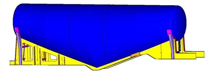
ABAQUS software was used for the finite element analysis, and a mixture of triangular and quadratic meshes with a mesh size of 15 mm was used for the mesh division.
2. Selection of simulation conditions for cement trailer finite element analysis
According to the actual load situation of cement tanker trailer, four working conditions, namely full load, unloading, turning and braking, are selected for the deformation and stress intensity analysis of the whole vehicle.
The conditions defined for each simulated working condition are as follows.
1)Full load working condition
The load on the vehicle is: the self-weight of the structure and 32300kg of material
The boundary conditions are: restraint at the traction pin and vehicle suspension
2)Under the unloading condition
The load on the vehicle is: the structure weight, 32300kg of material and 0.2MPa unloading pressure
The boundary conditions are: restraint at the traction pin and vehicle suspension
3)Under the turning condition
The load on the vehicle is: downward 1g acceleration, lateral 1g acceleration
The boundary conditions are: the traction pin and the vehicle suspension with restraint
(4) Under braking condition
The load on the vehicle is: downward 1g acceleration, forward 2g acceleration
The boundary conditions are: the traction pin and the vehicle suspension with constraints
where the barrel material is B600, yield strength ≥ 550MPa, tensile strength ≥ 600MPa.
Body underframe material Q345, yield strength ≥ 345MPa, tensile strength ≥ 490Pa; head material Q345, yield strength ≥ 345MPa, tensile strength ≥ 490MPa
3. Cement trailer finite element analysis of simulated working conditions
Analysis of full load condition
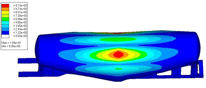
The full load condition simulates the cement bulker trailer driving on the road at a uniform speed when it is fully loaded, which mainly bears its own weight and the weight of the loaded material.
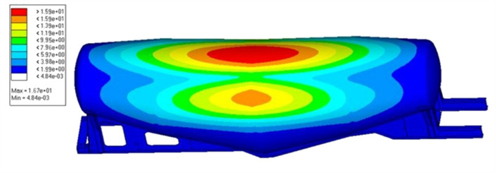
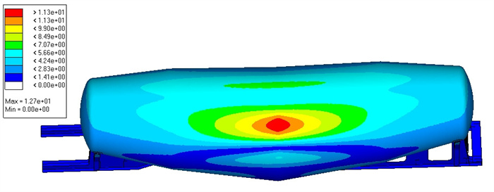
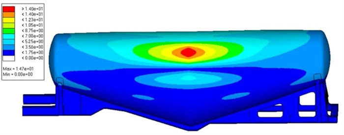
The displacement deformation of the cement bulker trailer under the simulated full load condition is shown in Figure 4-2, and the maximum deformation is
The maximum deformation is 10.9mm, which occurs in the upper two sides of the cylinder. Because the tank is designed with 4 sections of circular arc flexibility, the tank is allowed to have deformation and meet the design requirements.
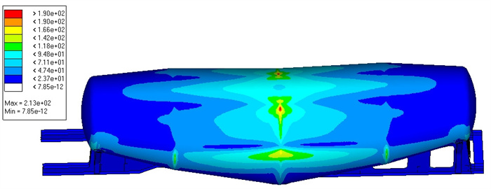
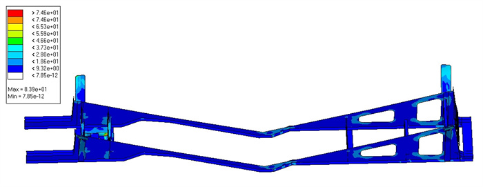
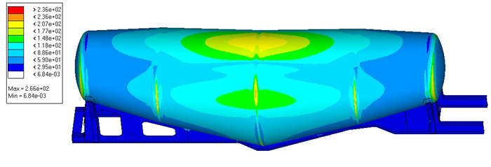
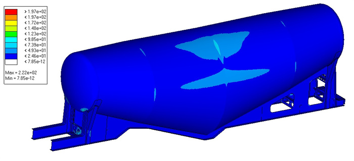
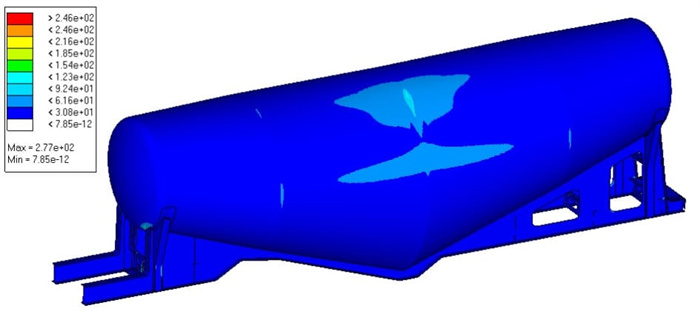
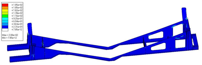
The maximum stress of the vehicle is 213MPa, which occurs at the upper two sides of the cylinder, and is less than the strength of the material used in the cylinder; the maximum stress of the chassis is 83.9MPa, which is located at the frame beam behind the traction pin, and is less than the strength of the material used in the chassis.
The maximum stress of the underbody is 83.9MPa, which is located at the frame cross member behind the traction pin, and is less than the strength of the material used in the underbody. The overall stress of the barrel and underbody frame is small, and the safety margin is relatively large to meet the design requirements.
4. Analysis of unloading conditions
The unloading condition simulates the unloading of the cement transport trailer when it is fully loaded, bearing the vehicle weight and material weight, and pressurizing the tank by 0.2MPa.
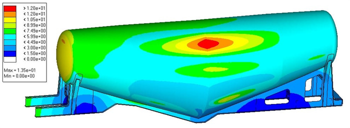
The displacement deformation of the cement trailer under the simulated unloading condition is shown in Figures 4-5, and the maximum deformation is 16.7mm, which occurs in the upper part of the tank.
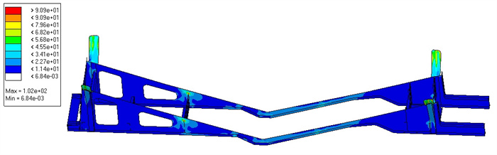
The maximum stress of the vehicle is 266MPa, which is located at the side part of the middle section of the cylinder, and is less than the strength of the material used in the cylinder; the maximum stress of the body bottom frame is 102MPa, which is located at the first cross beam of the upper part of the suspension of the body bottom frame, and is less than the strength of the material used in the body bottom frame.
The maximum stress of the underbody frame is 102MPa, which is located at the first cross-beam of the upper part of the underbody suspension and is less than the strength of the material used for the underbody frame. The overall stress of the barrel and the underbody frame is smaller and the safety margin is larger, which meets the design requirements.
5. Turning condition analysis
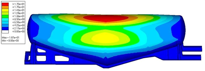
The cornering condition simulates the cornering situation of cement tank trailer when it is fully loaded, and the downward 1g acceleration and lateral 1g acceleration are applied to the vehicle for the analysis. The displacement of the bulk cement trailer under the simulated turning condition is shown in Figure 4-8, and the maximum deformation is 12.7mm, which occurs at the upper part of the barrel side.
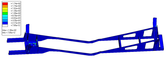
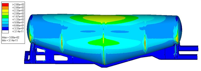
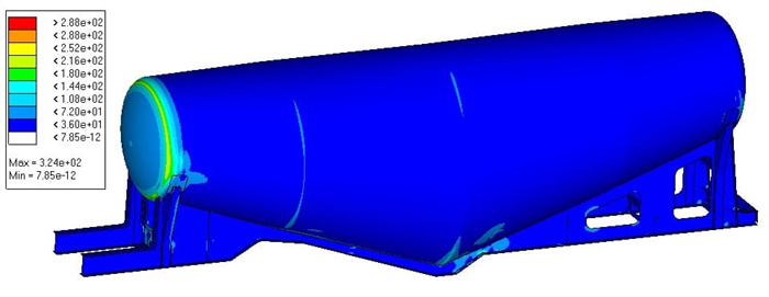
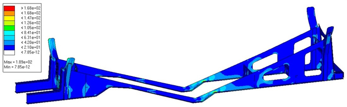
The stress cloud diagram of the dry bulk trailer as a whole and the bottom frame under the turning condition is shown in Figures 4-9 and 4-10, and the maximum stress of the vehicle
The maximum stress of the vehicle is 222MPa, which occurs at the lower part of the front end of the barrel and the bottom frame of the body, which is less than the strength of the material used in the barrel; the maximum stress of the bottom frame of the body is 196MPa, which occurs at the part of the frame where the traction pin is installed, which is less than the strength of the material used in the bottom frame.
The maximum stress of the underbody is 196MPa, which is less than the strength of the underbody material. The overall stress of the barrel and underbody frame is small, and the safety margin is large, which meets the design requirements.
6. Analysis of braking conditions
The braking condition simulates the emergency braking condition when the powder tank semi-trailer is fully loaded and encounters an unexpected situation during the travel. In the analysis, a downward acceleration of 1g and a forward acceleration of 2g are applied to the vehicle.
The displacement deformation of the powder tank semi-trailer under the simulated braking condition is shown in Figure 4-11, and the maximum deformation is 11.1mm, which is located at both sides of the upper part of the middle of the cylinder.
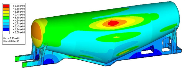
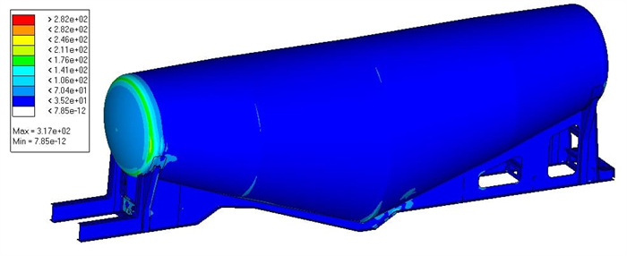
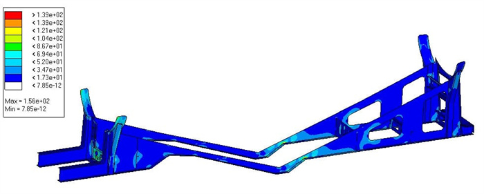
The stress clouds of the overall and underframe of the powder tank semi-trailer under the simulated braking situation are shown in Figure 4-12 and 4-13. The maximum stress of the vehicle is 317MPa, which occurs at the front lower part of the cylinder body and the underframe connection part, which is smaller than the strength of the material used for the cylinder body; the maximum stress of the underframe is 156MPa, which occurs at the front variable section part of the rear underframe, which is smaller than the strength of the material used for the frame. The overall stress of the barrel and underbody frame is small, and the safety margin is large to meet the design requirements.
7. Analysis of adjusted full-load working condition
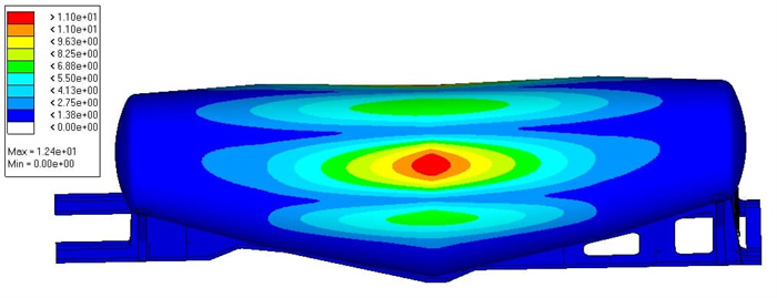
The adjusted full load condition simulates the powder tank semi-trailer driving on the road at constant speed when it is fully loaded, at this time, it mainly bears its own weight and the weight of the loaded materials, the displacement of the powder tank semi-trailer is shown in Figure 4-14, the maximum deformation is 12.4mm, which appears in the upper two sides of the cylinder body.
The maximum stress of the vehicle is 273MPa, which is located on both sides of the upper part of the barrel, less than the strength of the material used in the barrel; the maximum stress of the underframe is 138MPa, which is located at the cross beam of the underframe behind the traction pin, less than the strength of the material used in the frame. The barrel and the underbody frame meet the design requirements.
8. Analysis of unloading condition after adjustment
The adjusted unloading condition simulates the unloading condition of powder tank semi-trailer when it is fully loaded, bearing the vehicle weight and material weight, and pressurizing 0.2MPa into the tank.
The displacement of the powder tank semi-trailer under the adjusted simulated unloading condition is shown in Figure 4-17, and the maximum deformation is 18.7mm, which appears at the top of the cylinder.
The stress clouds of the powder tank semi-trailer as a whole and the bottom frame under the simulated unloading situation after adjustment are shown in Figure 4-18 and 4-19.
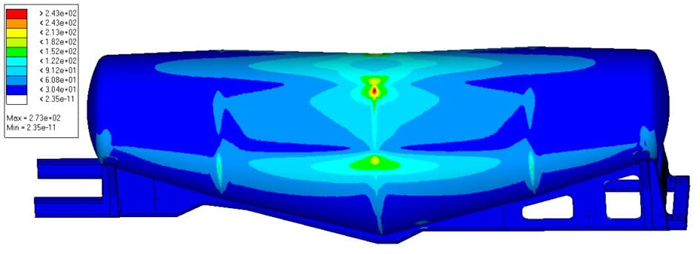
The maximum stress of the vehicle is 300MPa, which is located at the rear side of the barrel and is less than the strength of the material used in the barrel.
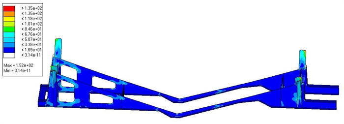
The maximum stress of the bottom frame is 152MPa, which is located at the reinforcement side support of the front end of the bottom frame, and is less than the strength of the material used in the bottom frame. Both the barrel and the underframe meet the design requirements.
9. Analysis of turning condition after adjustment
The adjusted turning condition simulates the turning condition of the powder tank semi-trailer when it is fully loaded, and 1g downward acceleration and 1g lateral acceleration are applied to the vehicle during the analysis.
The displacement of the powder tank semi-trailer under the adjusted simulated turning condition is shown in Figures 4-20, and the maximum deformation is 14.7mm, which occurs in the upper part of the middle side of the cylinder.
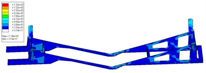
The stress cloud of the powder tank semi-trailer as a whole and the underframe under the simulated turning situation after adjustment is shown in Figure 4-21 and 4-22. The maximum stress of the vehicle is 277MPa, which is located at the lower part of the front end of the barrel and the connection part of the underframe, and is less than the strength of the material used for the barrel. The barrel and underbody meet the design requirements.
10. Analysis of braking conditions after adjustment
The adjusted braking condition simulates the emergency braking condition when the powder tank semi-trailer is fully loaded and encounters an unexpected situation in the process of traveling. In the analysis, 1g acceleration down and 2g acceleration forward are applied to the vehicle.
The displacement of the powder tank semi-trailer under the adjusted braking condition is shown in Figure 4-23, and the maximum deformation is 13.5mm, which appears in both sides of the upper part of the middle of the cylinder.
The stress cloud diagram of the powder tank semi-trailer as a whole and the underframe under the simulated braking situation after adjustment is shown in Figure 4-24 and 4-25.
It is smaller than the strength of the material used in the underbody frame. Both the barrel and the underframe meet the design requirements.
Summary
(1) This chapter simulates and analyzes the displacement and stress distribution of the powder tank semi-trailer under full load conditions, unloading conditions, turning condition,s and braking conditions.
Displacement and stress distribution; through the analysis, it can be seen that the deformation and stress of the vehicle under the four working conditions meet the design requirements, and there is a relatively large safety margin, so the lightweight design can be continued.
(2) According to the preliminary analysis results, the thickness of the barrel and body underframe web and wing plate were thinned, and the re
Four kinds of simulated working conditions were analyzed, and the deformation and stress of the vehicle after the thinning met the design requirements, and the weight was reduced by 400kg compared with the original design, with a weight reduction ratio of 5%, which achieved the purpose of lightweight.