1. Tank structure design
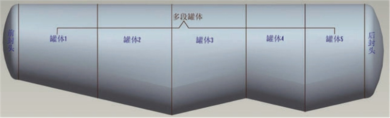
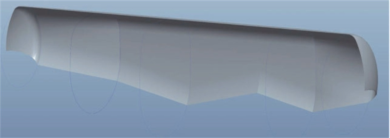
Cement trailer tank comprises a front head, back head, and multi-sectional tank splicing.
In Figure 4, for example, the “double-bin” tank is equipped with a 13° or 14° angle, mainly to meet the angle required for the material to reach the fluidization state. Among them, tank 1 and tank 5 and the end of the head butt, the tank cross-section is round to facilitate the butt between the head and the tank; because the front and rear direction of the tank has a particular inclination and the width of the tank shall not exceed 2.5m, which makes the rest of the tank body between the cross-section design of long circular cross-section, that is, the tank body cross-section consists of four segments of arc, the upper and lower part of the cross-section is an equidistant arc, and the two sides of the cross-section is a central arc. The side arcs are generally tangential to the upper and lower arcs.
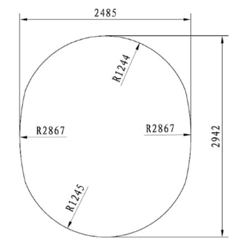
Restricted by the width of the traditional tank design method, the space on both sides of the top arc of the tank is not fully utilized, so in the same length, change the existing tank cross-section shape but still can increase the adequate volume of the tank.
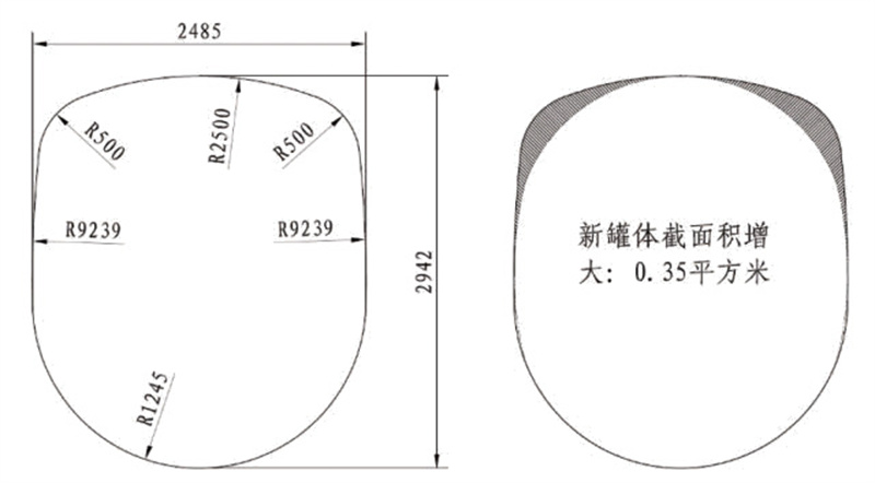
At present, the tank cross-section of domestic liquid tankers for transporting oil products adopts the rectangular structure; under the same width and height conditions, the cross-sectional area of the tank is much larger than that of the Cement trailer. The cross-sectional area can be increased by 0.35m2 accordingly (Figure 6), and the newly designed tank volume can reach about 50m3 for the 47m3 double-bin model, for example.
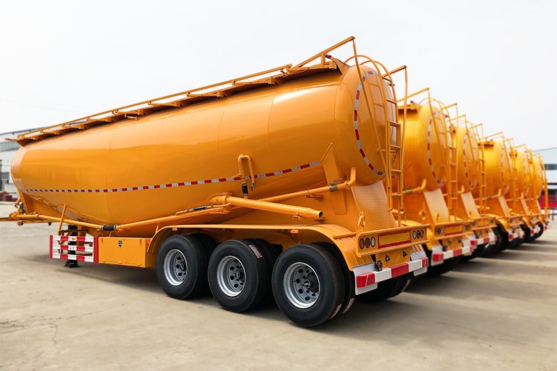
2. Powder tank semi-trailer structure introduction
Take the double bin (W type) powder tank semi-trailer as an example, the volume is 50m3, the overall mass is about 9250kg, the powder tanker working pressure is 0.2MPa, the tank body plate is 4mm T610L steel plate, for T610L high strength steel, the yield strength of the material is ≥500MPa.
Tensile strength of 550MPa ~ 700MPa, elongation ≥ 18%. Powder tank semi-trailer mainly consists of tank body assembly, frame assembly and travel mechanism, etc., where the tank body assembly contains the tank body, fluidization system, and reinforcement device, etc. The lower part of the tank body is welded to the frame and supported by multiple frame crossbeams and left and suitable longitudinal beams. The fluidization system is installed inside the tank, and the slide plates in the fluidization system are welded on both sides of the lower part of the tank. There are a lot of support plates welded on the lower part of the slide plate, so the deformation of the tank at the bottom and the upper part of the slide plate is small.
3. finite element analysis model simplification
The tank body is subjected to local stress mainly in several working conditions such as rapid braking, rapid turning and unloading, among which the tank body is subjected to the most excellent stress value when unloading under pressure, so only the tank body of unloading working condition needs to be analyzed statically, and the internal reinforcement of the tank body is optimized through the static analysis.
Assuming that the welding between the tank body and the tank body is reliable for force and moment transmission, the influence of manufacturing factors such as residual stresses in the manufacturing process and process factors that have little impact on the overall structure (e.g., small rounded corners, chamfers and welds, etc.) can be ignored, as well as the compressed air discharged from the air compressor through the fluidized zone during the discharge condition. Considering the symmetrical layout of the tank, only 1/2 of the upper tank of the fluidization system was modeled and analyzed to view the tank stress and tank deformation more quickly and clearly.
4. Finite element analysis of the reinforced tank model
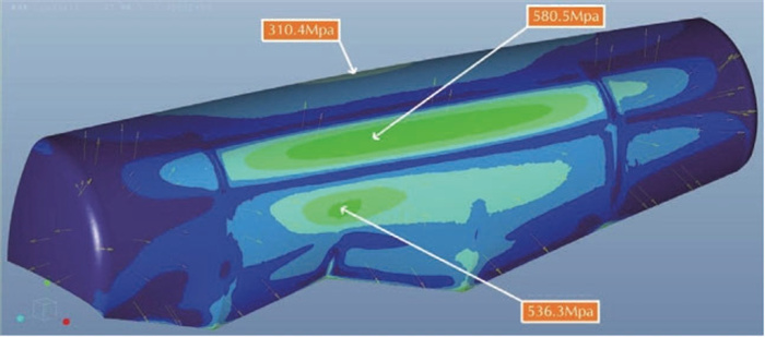
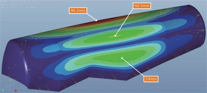
(1) Model analysis when no reinforcement device is installed
When no reinforcement device is installed inside the tank, the force analysis is performed on 1/2 of the tank. The analysis clouds (Figure 8 and Figure 9) show that the maximum stress on the tank is 580.5 MPa, which is located on the top side arc of the tank; the rest is distributed on the top and side of the tank, and the maximum stress on the top of the tank is 310.4 MPa, and the maximum pressure on the side of the tank is 536.3 MPa. The maximum deformation of the tank is 96.1mm, located in the top of the middle section of the tank, the maximum deformation of the top side arc of the tank is 60.5mm, and the maximum deformation of the side tank is 59mm. Reduce the amount of deformation of the tank.
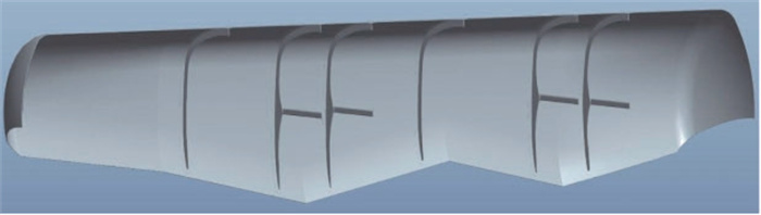
(2) Model analysis when reinforcement device is added
Two sets of reinforcement devices with a cross bracing structure are added at the middle of the tank in the front and rear bins.
The reinforcement device consists of a reinforcement plate pad, reinforcement plate, and transverse tension brace welded on the reinforcement plate. The reinforcement plate is ring-shaped and protrudes in the middle to facilitate the welding of transverse bracing, the thickness of which is 6mm, the thickness of the reinforcement plate pad is 4mm, and the transverse bracing is 60×40 plate folded channel steel structure, the thickness of which is 5mm.
In addition, in the front warehouse and after the warehouse tank butt weld and the front warehouse tank and head butt.
The reinforcement device is composed of a reinforcement plate and plate pad, of which the reinforcement plate presents a ring structure, the thickness of the reinforcement plate is 6mm, and the thickness of the reinforcement plate pad is 4mm.
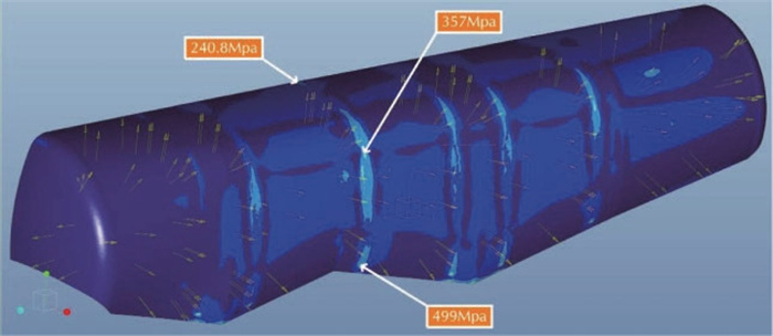
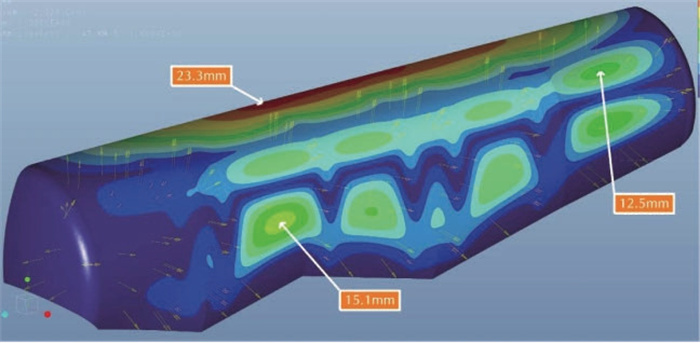
By analyzing the cloud, we can conclude that the maximum stress on the tank is reduced to 499 MPa, which is located at the end of the reinforcement plate in the ring-shaped reinforcement device at the butt weld of the front and rear bins; the rest is distributed on the top of the tank and the top side arc, and the maximum stress on the full tank is 240.8 MPa, and the maximum focus on the top side arc is 357 MPa. The maximum deformation of the tank is reduced to 23.3 mm. Located at the top of the middle section of the tank, the maximum deformation on the top side arc was 12.5mm and the maximum deformation of the side tank was 15.1mm.
Through the finite element analysis of the new Cement trailer tank structure and the rational arrangement and optimization of the internal reinforcement device, the stress value/deformation on the tank was reduced by 81.5MPa/72.8mm compared with that before the reinforcement device was added. T610L material tensile strength and elongation range, so the design of the new Cement trailer tank is feasible, it can meet the Cement trailer in line with the premise of regulations, the adequate volume of the Cement trailer increased by about 3m3, but also to meet the powder tank semi-trailer design requirements of each type, to meet the market personalized It can also complete the design requirements for each kind of powder tank semi-trailer and satisfy the individual needs of the market.